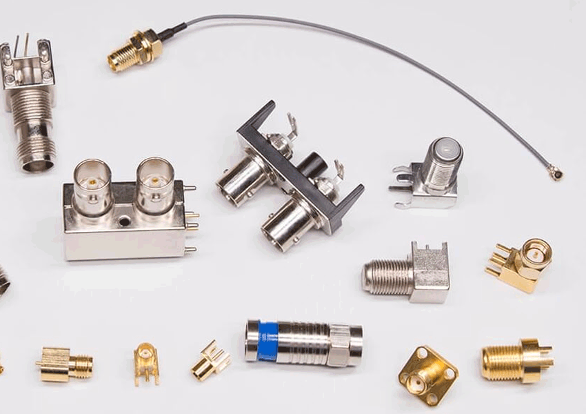
The radio frequency coaxial connector is a general term for the connector used in the radio frequency coaxial feeder system. The connector is used to connect the radio frequency coaxial cable in the radio frequency transmission line used in communication and electronic equipment and similar electronic equipment. Or the connection between coaxial and microstrip, coaxial and waveguide. Its plug part is often installed on the end of the cable, and the socket part is often installed on the equipment fixing unit, and is also often used for the connection between two radio frequency cables. Radio frequency coaxial connectors are also called RF connectors. “R” is the first letter of RADOI (radio frequency), and “F” is the first letter of FREQUENCY (frequency).
Professional features of RF coaxial connectors
1. Many varieties and specifications: more than 20 international general series, more varieties and specifications.
2. Rely on mechanical structure to ensure electrical characteristics. It is a mechatronic product, which is essentially different from other low-frequency connectors.
3. Parts processing is mainly turning machining, and assembly manual work is too much, it is difficult to carry out automated assembly.
4. Product update is slow.
5. It is an important part of the electrical connector, and it is a labor-intensive product with a certain technical content.
6. Product reliability, failure modes and failure mechanisms are complex.
The choice of radio frequency coaxial connector
There are five main factors in choosing RF coaxial connectors:
1. Interface mechanism type
The connection mechanism of the connector is not only to provide convenient and fast connection or separation of the coaxial transmission line, but also to provide stable electrical performance and environmental protection devices. When there is not enough space to rotate the connection nut in the use occasion, a non-twist type connection should be selected. mechanism. In addition, for frame connectors, non-twisting connection mechanisms are also very useful.
2. Electrical performance
ACharacteristic impedance: the connector should match the impedance of the transmission system and cable, otherwise it will cause the system performance to decrease
B. Withstand voltage: The maximum withstand voltage of the connector should meet the withstand voltage requirements of the system.
Generally speaking, if it is a wideband application, some favorable broadband impedance matching characteristics should be sacrificed to obtain the required high voltage rating.
C Maximum work efficiency

3. Cable connection method and cable type.
A cable connection: There are two ways to connect the connector cable: one is welding the center conductor, and the standard tightening method of combing the braided wire is still common. It is especially suitable for occasions without special installation tools and is convenient for on-site maintenance. two. The clamping method of welding the center conductor and crimping the braided layer. Because of the high working efficiency of the crimping method. Reliable termination performance and good consistency have become a common method today.
B cable type: The appropriate connector should be selected according to the characteristics of the various cables used (such as flexible cables, semi-rigid cables, corrugated conductor insulated cables, foam insulated cables). Generally, cables with small outer diameters are matched with small connectors.
4. Termination form
connectors can be used for radio frequency coaxial cables, printed circuit boards, machine frame drawer type functional components and their connection interfaces.
5. Material and plating
The shell and inner conductor are mainly brass, beryllium copper, tin bronze, and the insulating material is mainly tetrafluoroethylene.
The center conductor is generally plated with silver or gold, and the outer shell is plated with nickel or silver. SMA, SMB, SSMB, SMC outer conductors are all gold-plated.
RF coaxial connectors are used to transmit RF energy, and the frequency range can reach 18GHz or higher. The basic structure includes:
Male and female neutral contacts, the outer interface material, the outermost is the contact, the outer part plays the same function as the outer shield of the cable: it transmits signals and the shield is grounded.
