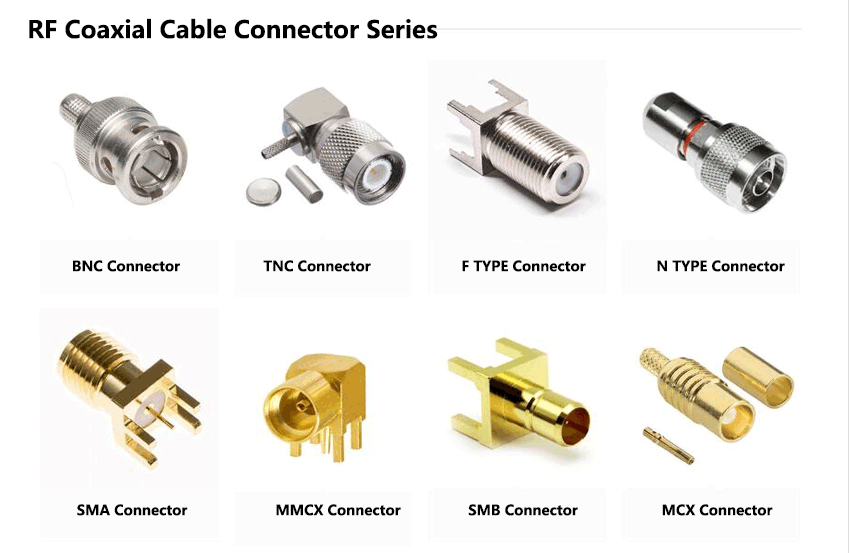
RF coaxial connectors must not only realize the mechanical connection between the transmission lines, but also complete the task of transmitting as much high-frequency electromagnetic energy as possible. The materials and mechanical dimensions used in the connector design have an impact on the high-frequency transmission performance. Almost all have a certain influence, especially the internal dimensions. These materials and dimensions establish (determine) the characteristic impedance of the transmission line. The characteristic impedance of the connector must be close to the characteristic impedance of the system, otherwise the obvious impedance mismatch will cause significant signal reflection problems , This can’t perform the function of RF coaxial connector to transmit as much high-frequency electromagnetic wave energy as possible.
Although the coaxial connector is a coaxial structure, the essential characteristics of the connector (such as the existence of the connection interface-the change of the medium, the need for fixing the inner conductor and the medium) are doomed to the inner and outer diameter of the conductor and the dielectric material of the connector. For example, the appearance of barbs and knurls. In order to reduce signal reflection, it may be necessary to properly compensate for steps or grooves. In this irregular structure, the propagation of electromagnetic waves is extremely complicated, but In order to reduce the reflection of the signal, we have to grasp the transmission characteristics of the signal in this complex structure. In this case, it is wise for us to borrow advanced analysis tools.
Therefore, the finite element analysis of electromagnetic waves is now commonly used in high-frequency signal transmission, such as HFSS and CST software. The great advantage of this analysis tool is that we can compare our models before making samples and test samples. The high-frequency transmission performance of the product is analyzed, modified, and optimized until the analysis structure is satisfactory. Then it is put into sample preparation and testing. Of course, due to the certain difference between the analysis model and the actual sample, the analysis result must be different from the actual test result A certain gap. However, in actual simulation analysis, the model is often optimized to a certain performance, so that there is generally enough space to absorb the variation of production, assembly and testing. There is a certain gap between the finite element analysis results of electromagnetic waves and the actual test results. The main reasons are as follows:

There is a difference between the actual test interface and the model interface;
The performance of the cable in the model is ideal, but the dielectric constant and size of the cable medium vary in practice;
The dielectric constant of the connector’s medium cannot be accurately controlled;
There may not be the required calibration parts during the test, and the data is often measured by means of adapters or gating;
In order to reduce the complexity of the analysis, subtle structures are often omitted, such as small air gaps being replaced by the medium, and the interference between barbs and the medium;
During assembly, it is unavoidable that the parts are compressed and deformed and the relative position of the parts is inconsistent with the model due to deformation;
When modeling, the fillet of the part is often changed to chamfer, or even the feature is ignored;
The nominal size is used when modeling the connector, but the actual parts have tolerances;
There are certain errors in the simulation analysis itself, and 100% accuracy cannot be guaranteed;
10.When the connector is connected to the cable by crimping, the deformation of the cable is large, and the variation is also large, and the model often cannot reflect this situation.
