In RF circuits, it is often necessary to use RF devices with various interfaces (e.g. SMA, SMP, BNC, etc.). In order to connect these RF devices and equipment, we need to use RF wire harnesses, connectors and adapters. However, regardless of the type of RF interface, did you know that the most common is 50 ohms? We commonly use signal sources, spectrum analyzers, network analyzers and so on these instruments interface are 50 ohms. Here we still have some doubts, why do so many devices or instruments interface how all choose 50 ohms?
Why 50 ohms?
Let’s start by understanding transmission lines, which are utilized to distribute signal energy. Various types of transmission lines exist, including coaxial cables, microstrip cables, ribbon cables, and more. Common RF cables are coaxial cables, which generally consist of an inner conductor, an insulator, an outer conductor, an insulating layer and a sheath.
Coaxial Cable
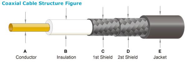
Inner Conductor: A wire made of a metallic material (such as copper or aluminum) that is responsible for transmitting signals.
Insulator: People usually make the insulator of RF Cable from materials such as polyethylene, polyvinyl chloride, polytetrafluoroethylene, and other materials. The insulator keeps the cable’s internal conductors isolated from the external environment.
Outer Conductor (shield): consists of a metal mesh shield, usually made of copper or aluminum, used to shield the external electromagnetic interference, to protect the inner conductor from interference.
Insulation: Insulation material located outside the outer conductor, usually made of materials such as polyethylene (PE) or polyvinyl chloride (PVC), used to protect the cable from physical damage.
Sheath: Manufacturers usually make the outer sheath of RF cable from polyvinyl chloride, polyethylene, and fluoroplastics. The outer sheath is the material that protects the internal components of the cable.
The impedance of the transmission line and the system’s impedance matching determine the transmission of maximum power and the reflection of minimum signal. The impedance of the transmission line we call the characteristic impedance or the characteristic impedance. The characteristic impedance can be expressed by the following equation:
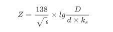
- D: inner diameter of outer conductor
- d: outer diameter of the inner conductor
- ε: the dielectric constant of the filling medium
- ks: inner conductor coefficient, related to the inner conductor structure.
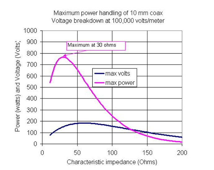
From the formula we know that the characteristic impedance is related to the dimensions of the conductors inside and outside the transmission line and the dielectric constant of the filling medium. By manipulating these three parameters, it is possible to regulate the characteristic impedance. Transmission lines serve the purpose of energy transmission and consequently have a need for maximum power. The maximum withstand power is related to the dimensions of the inner and outer conductors and the characteristic impedance.
E: The strength of the electric field, when it reaches a certain strength when the breakdown;
D: Inner diameter of the outer conductor.
d: Outer diameter of the inner conductor.
Hence, it is necessary to choose an appropriate characteristic impedance to ensure optimal transmission of signal power and prevent signal power loss.
30 Ohms and 77 Ohms
Here again to mention the famous Bell Labs, Bell Labs in different parameters of the coaxial cable to do a lot of experiments, found that the coaxial cable and its characteristic impedance in 30 ohms when the signal power to withstand the largest, and in the 77 ohms when the signal loss is the smallest.
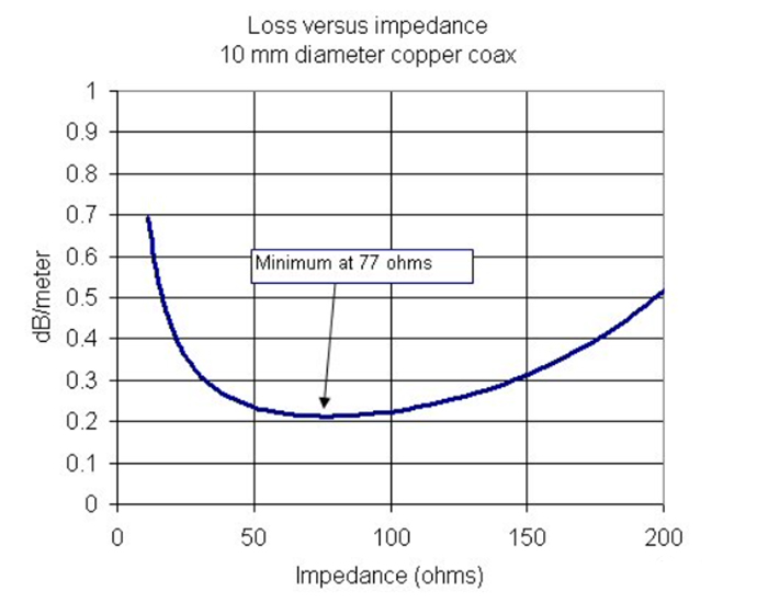
This is the reason that the impedience of the input or output port that we find in a typical RF device or equipment is also basically 50 ohms. As a result, RF circuits are also designed to have an impedance matching 50 ohms.
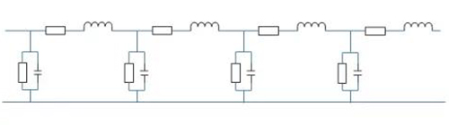
Another thing to note is that the impedience here does not mean that the resistance of the wire inside is 50 ohms. If you use a multimeter to measure the resistance on both sides of the wire, you will see that it reads 0. In fact, it refers to the impedence of the entire transmission line system. In summary, we can think of a transmission line as a circuit of n resistors, capacitors, and inductors, which we can represent as the equivalent circuit below:
The Importance of Impedance Matching
Resistance, inductance and capacitance in a circuit all act as a barrier to current, and we call the barrier to current in a circuit an impedance.
Impedance consists of two parts, resistance and reactance, where reactance includes inductive and capacitive reactance. Impedance can be expressed as a complex number, where resistance is the real part of the complex number and reactance is the imaginary part of the complex number.
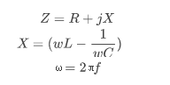
- Z: Mpedance
- X: Reactance
- wL: Inductive Reactance
- 1/wC: Capacitive Reactance
- f: Frequency of the Signal
- ω: Angular Frequency
From the formula for impedance, it is clear that the resistance of an ideal pure resistor is independent of the signal frequency. However, in practice, circuits or systems contain resistance, inductance and capacitance, and the magnitude of inductive and capacitive reactance is frequency dependent. Hence, the presence of inductive and capacitive reactances in a circuit or system becomes significant when dealing with high frequency signals.
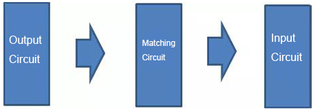
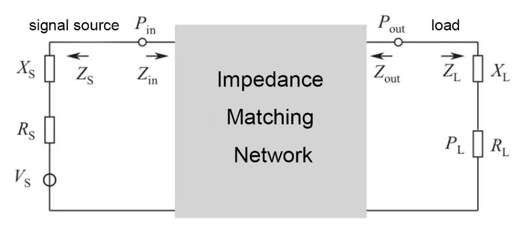
RF signals are categorized as high frequency signals, distinguishing them from low frequency signals. In addition to resistance, circuits carrying RF signals often require consideration of inductive and capacitive reactance. For low-frequency circuits, the circuits transmit waveforms such as current and voltage, while RF circuits need to transmit power from the transmitter to the receiver. In the process of transferring power from one circuit to another it is necessary to try to ensure the power and quality of the signal. One of the most important things you can do to ensure this is to match the impedience of the circuit, that is to say, to match the impedience of the input and output circuits correctly.
Impedance matching is necessary for the interface section of RF circuits, just like in other circuits. If the interface section of the RF circuit is not well-matched, the signal will bounce back and forth at the interface, leading to a decrease in the power of the signal transmitted to the other circuit. Due to the short wavelength of the high-frequency signal, it combines with the original signal upon reflection, resulting in distortion and a degradation in signal quality. In addition, there will also be interference signals from the outside world entering the circuit. This makes it impossible to transmit RF signals correctly without proper impedance matching.
Students who have experience in amplifier debugging should be familiar with the situation where self-excitation phenomenon occurs in the amplifier circuit due to improper matching of the amplifier port. This is why we often add attenuators at both ends of the RF amplifier, in addition to attenuating large signals, but also to prevent self-excitation due to impedient mismatch of the amplifier port.
In RF circuits or RF systems, impedance matching is a critical work, matching good or bad affects the direct system or circuit signal transmission, the performance of the system or circuit has a very big impact.